Global CNC Manufacturing with VERICUT
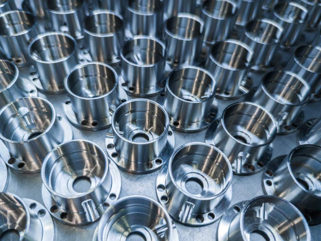
Companies of all sizes, all over the world use VERICUT CNC simulation, verification and optimisation software to improve their manufacturing processes.


For Tebis, automation is a key principle for effective and efficient CNC programming while improving machining quality, efficiency and safety. The latest release of Tebis 4.0 R8 has added additional capabilities for more automation.
CAM: Automation: clearer operating structures in the revised feature scanner
The ‘Auto’ function is also convenient: The component is completely scanned with no interruption, and clearly evident features are automatically inserted. If several different features are possible for a machining operation, users can jump right to the appropriate areas after scanning and select the desired feature.
CAM: Machine technology: quickly and easily create tool assemblies
The insert length for tool assemblies can be determined at the click of a button. A line at the diameter of the cutter is drawn parallel to the tool axis. The intersection point between this line and the shank contour yields the insert length.
CAM: Milling
Machining time is significantly reduced. The machine spindles are subject to lower loads due to machining in the axial direction. Side milling and downward machining can be easily combined, so users can fully benefit from the advantages of both strategies
CAM: Job planning: more collision checking in multiple set-ups
For components in multiple set-ups, the blanks for adjacent components are now also fully accounted for by collision checking with the CNC simulator.
Laser hardening
The fully integrated solution includes manufacturing preparation allowing for the automatic generation of curves. Integrated collision checking it supports the simple and intuitive calculation of NC programs for laser hardening systems. The hardened areas are coloured differently depending on the intensity of the laser irradiation which helps to evaluate whether the laser passes over the part at certain points or remains in position.
Laser weld cladding
The ‘Pocket’ function in the ‘LClad’ module can be used to automatically generate NCJobs for laser weld cladding to fill pockets. The software automatically accounts for holes and excludes it from cladding. Operators can also easily create complex toolpaths with the integrated simulation and collision checking functions.
CAD: Reverse engineering: more automation and clear presentation of the results
As the basis for reverse engineering, you create a wire-frame model from digitised data, which in turn is used to create a surface model. The surface model can now be generated automatically.
Faster machining with indexed collision avoidance
The function for residual stock machining provides a new and highly convenient strategy for collision avoidance with indexed tilt determination. This strategy automatically detects and connects milling areas that can be machined collision-free with the same tilt direction.

The corresponding tilt direction is also calculated and areas that can’t be machined without collisions are deactivated and can be selected in the continuation job. Flexibility is maintained and users can also manually subdivide the milling areas as desired.
Shorter run times and fewer machine movements in 5-axis simultaneous avoidance milling
The function for 5-axis simultaneous avoidance milling has been comprehensively improved. Specific milling areas that can’t be machined collision-free in an NC job calculated using the collision avoidance.
5-axis simultaneous deburring, also with tapered cutters
Edges that don’t lie on the same plane in space can now also be processed by automatic multi-axis simultaneous deburring with tapered cutters. You can also specifically select whether you want to machine the component in climb cut, conventional cut or lace cut mode. Machining of sharp edges and corners has also been optimised.
Integrated simulation
Integrated simulation ensures collision protection before NC output. Travel behaviour and switching of drill bushes and drill bush holders are simulated with absolute precision in the virtual CAM environment.
CAM: Job planning: collision checking in multiple setups
For components in multiple set-ups, the blanks for adjacent components are now also fully accounted for by collision checking with the CNC simulator.
Tebis (UK) www.tebis.com