Global CNC Manufacturing with VERICUT
Companies of all sizes, all over the world use VERICUT CNC simulation, verification and optimisation software to improve their manufacturing processes.


Vericut Machine simulation detects collisions and near-misses between all machine tool components such as axis slides, heads, turrets, rotary tables, spindles, tool changers, fixtures, workpieces, cutting tools, and other user-defined objects. Users can also set up ‘near-miss zones’ around components to check for close calls and detect over-travel errors. Machine movements and material replacement can even be simulated while stepping or playing backwards.
The software simulates all types of CNC machining, including drilling and trimming of composite parts, waterjet, riveting, robots, mill-turn and parallel kinematics. It operates independently, but can also be integrated with leading CAM systems including Dassault Systemes Catia, Siemens PLM NX, Autodesk PowerMill and Vero Edgecam.
Version 8 features several enhancements designed to increase the ability of manufacturing engineers to analyse, optimise, and document the CNC programming and machining process. Intelligence gathered from both the cut part and the machining process is applied to achieve an even higher level of accuracy and efficiency.
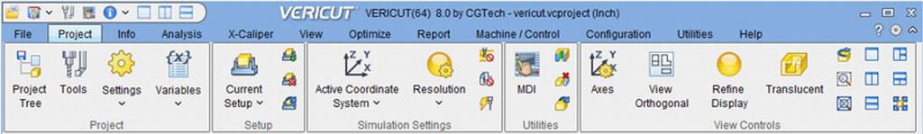
“Vericut 8 is all about optimising our customers’ workflow to quickly access only the menu choices needed at the time,” states CGTech’s managing director, John Reed. “For example, the new Ribbon Bar has been developed to help users find the functionality they need quickly and with minimal mouse clicks.”
CAD/CAM programmers and manufacturing engineers now have the ability to optimise ‘Air Cuts Only’ focusing on the milling cutter motions away from the raw material. This capability is included within the base Verification license, and this new method is intended as an easy-to-use, entry-level technique of optimising NC programs. Additional optimisation strategies are available with the optional OptiPath or Force modules.
Vericut V8’s Step file interface reads files containing AP203 and AP214 (geometry only) protocols. A Step file can be referenced directly in Vericut’s modelling interface to describe machine, stock, fixture, and design shapes, or 3D cutting tool shapes in Vericut’s Tool Manager which displays the CAD geometry window that allows users to identify which parts of the CAD model file correspond with holders, cutters, or inserts.
As with all software programs, the accuracy of the data input will directly affect the output so an accurate model of the cutting tool and holder is required for the effective and accurate simulation of the machining process.
Most leading cutting tool manufacturers now make 3D solid model data available which Vericut can read in for use in the simulation process. Many of the 3D models are available via the Machining Cloud app, and Version 8 has been enhanced to take advantage of more Machining Cloud metadata.
Vericut also integrates with most major tool management systems and presetting suppliers including Zoller and Speroni can also interface to the software, so tool offsets and exact dimensions can be applied to the simulation session.
A new preferences dialog allows users to set-up multiple default settings that help to streamline creation of cutting tool assemblies. For example, specifying the colours used, the driven point offset numbering scheme, CAD model tolerances for cutters and holders, and if the holder is desired (or not) for a new tool. Each imported 3D tool model can also have its own separate model tolerance.
The Vericut logger now displays messages and reports from many sources in a tabbed logger window. In addition to errors, warnings, and other messages from the Vericut session, it also displays information from Auto-Diff and X-Caliper.
Additionally, a new ‘Toolpath Trace’ feature creates a wireframe of the motion path that can then be measured. In NC Program Preview or Review modes, picking on a toolpath trace in the wireframe automatically sets the simulation to that record in the NC program.
The Force module, first available with the release of Version 7.4, determines the maximum reliable feed rate for a given cutting condition based on four factors: force on the cutter, spindle power, maximum chip thickness, and maximum allowable feed rate. In this latest version, there are new features for better control of entry/exit speeds, ‘clean-up’ feed rates, and tooling information has been re-arranged to be more intuitive.
Several additional new features include the ability to translate models via selecting solid model features, eliminating the need to create co-ordinate systems for positional information. Enhanced modelling options in version 8 provide greater control and flexibility over moving individual models, assemblies, and component origins, greatly reducing time to model machines, especially from 3D CAD model assemblies.
Mr Reed concludes: “We have worked with end users and machine tool manufacturers to create accurate and effective virtual machine tool configurations. These range from simple 3-axis milling machines to multi-axis machining centres; simple 2-axis lathes to complex mill-turn centres with sub-spindles and robot loading; waterjet and laser cutting, and machining/polishing robots. Vericut simulates all machine tool brands.”
CG Tech www.cgtech.co.uk